A
jib crane is only as safe as its installation. Industry experience consistently shows that a large share of jib crane problems—premature wear, structural cracks, unstable loads—can be traced back to the day the crane was installed: an undersized foundation, a column set out of plumb, bolts that were never torqued to spec, or a load test that never happened.
This guide walks through the entire installation process from site assessment to final load testing, whether you’re installing a freestanding column crane, a wall-mounted unit, or a mobile jib. A note before we start: foundation work, structural connections, and electrical wiring should be performed by qualified personnel, and every step must follow the manufacturer’s manual where it differs from general guidance here.
Before You Begin: Planning and Site Assessment
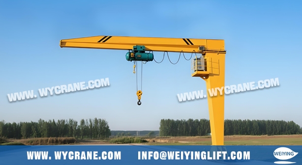
Good installation starts days before the crane arrives.
| Installation Type | Foundation | Rotation | Key Requirement |
| Freestanding column | Dedicated concrete foundation | Full 360° | Correct bolt pattern and curing time |
| Wall-mounted | None (bolts to wall) | 180–200° | Structurally adequate wall verified by engineer |
| Mobile jib | None (counterweighted base) | Full rotation, portable | Lower capacity, traded for flexibility |
Confirm the installation type. Freestanding column cranes need a dedicated concrete foundation and offer full 360° coverage. Wall-mounted cranes save floor space but require a structurally adequate wall and typically rotate 180–200°. Mobile jibs on counterweighted bases skip concrete entirely but trade capacity for flexibility. The type determines everything that follows.
Verify the foundation requirements. Pull the manufacturer’s foundation drawing and check it against your site: concrete class (typically C25/C30 or better), slab thickness, anchor bolt size, embedment depth, and edge distances. Compare the required bolt pattern against your floor—relocating anchor bolts after pouring concrete is an expensive mistake.
Plan the work zone. Map the crane’s rotation radius and confirm it clears racking, overhead cranes, walkways, and building columns. The load path from delivery point to final position must be clear, and you need overhead access or a forklift for the heavier components.
Prepare tools and crew. Typical needs: torque wrench (calibrated), spirit level or laser level, plumb line, lifting equipment rated for the components, and a two-to-three-person crew.
Unpack and verify. Check the delivery against the parts list before anything else. Look for transport damage—bent arm sections, damaged bearings, missing hardware—and resolve claims immediately. Verify the capacity plate, manuals, and certificates are included.
Step 1 – Preparing the Foundation
For freestanding cranes, the foundation carries every load the crane will ever lift. Rushing this stage is the single most common installation error.
Lay out the anchor bolt positions using the manufacturer’s template and confirm the orientation: the arm’s home position, the direction of rotation, and clearance from obstructions. Anchor bolts must be set plumb and at the correct projection height, with threads protected during the pour.
Check the embedment plate or bolt cage for level before concrete is placed—an out-of-level foundation can never be fully corrected later.
Respect the concrete curing time. Concrete reaches design strength in 28 days under normal conditions, and most specifications allow loading at 70–80% of strength after roughly 7 days. Installing a column on green concrete invites settlement and bolt failure. For wall-mounted cranes, have a structural engineer verify the wall can handle the moment loads, and add a support column or knee braces where required.
Step 2 – Mounting the Column
With the foundation ready, set the column onto the anchor bolts.
Use a plumb line, level, or theodolite to check verticality in two perpendicular directions. Tolerance is typically 1–2 mm per meter of height—follow the manufacturer’s specification. Never pull a leaning column straight with the anchor bolts; correct it with leveling nuts, shims, or grout.
Tighten anchor nuts in a star or cross pattern, in at least two stages, to the specified torque. On tall columns, re-check plumb after the first pass—tightening can shift alignment.
Where the design calls for it, pour non-shrink grout under the base plate after final alignment, and allow it to cure before applying full load.
Step 3 – Installing the Jib Arm and Rotation Bearing
The rotation bearing connects the arm to the column and carries both vertical and moment loads—treat it carefully.
Clean mounting surfaces and check the bearing for smooth rotation before assembly. Bolt the bearing to the column per torque spec, then lift the arm into position. Component weights here often exceed what a crew can handle manually—use proper lifting equipment and never let anyone under a suspended part.
Bolt the arm to the bearing, torque to spec, then rotate the arm through its full travel by hand. Motion should be smooth and uniform, without flat spots, noise, or binding. Install and adjust the rotation stops so the arm cannot collide with walls, columns, or electrical drops.
Step 4 – Installing the Hoist and Trolley
Mount the trolley onto the arm’s track first, then fit the hoist. Check trolley-to-track clearances per the manual—too tight causes premature wheel wear; too loose allows racking.
Electrical work comes next. Run the power supply to the crane with a dedicated circuit breaker, bond and ground all metal parts, and route the pendant cable or festoon system so it never fouls the rotation. Wire the emergency stop into the control circuit so it cuts all motion, not just the hoist.
Test pendant or radio remote functions: up, down, rotation, and e-stop. On variable-frequency drives, set acceleration and deceleration ramps to smooth, controlled values—factory defaults are often too aggressive and will cause load swing from day one.
Step 5 – Alignment and Pre-Commissioning Checks
Before any load touches the hook, run a complete commissioning checklist:
- Re-torque every structural bolt against the torque table—initial tightening relaxes as components seat
- Verify all limit switches (upper/lower hoist limits, rotation stops) trigger correctly
- Lubricate every grease point: rotation bearing, trolley wheels, hoist drum, and rope as specified
- Confirm the load rating label and safety decals are legible and in place
Step 6 – Load Testing and Acceptance
Load testing is not optional—it is the proof that the installation actually works.
No-load test. Run every motion through full travel several times. Listen for unusual noise, watch for jerky motion, and confirm brakes hold the hook at any point.
Static load test. Typically 125% of rated capacity (verify against your standard and manufacturer), lifted just clear of the ground and held for 10 minutes. The crane must show no structural movement, no slippage, and no permanent deformation.
Dynamic load test. Typically 110% of capacity, lifted and moved through all motions as in normal operation. Brakes, limits, and controls must function correctly under load.
Record everything: date, loads used, deflection measurements, bolt torque values, test duration, and sign-off by the responsible person. This documentation is your baseline for future inspections and often a regulatory requirement.
Common Installation Mistakes to Avoid
Installing on green concrete. The most frequent—and most consequential—shortcut.
Ignoring verticality tolerances. A leaning column loads the bearing unevenly and accelerates wear on every moving part.
Under-torqued or single-pass bolt tightening. Bolts loosen under vibration; two-stage star-pattern tightening with a calibrated wrench is the minimum.
Skipped grounding. A missing ground turns a fault into a shock hazard.
Unadjusted limits. The first over-hoist can wreck the hoist and drop the load.
Skipping the load test. “It looks fine” is not a commissioning criterion.
Post-Installation: Inspection and Maintenance
The first month matters most. Re-torque anchor and structural bolts after the first weeks of operation, check for foundation settlement, and watch for any drift out of plumb.
Finally, make sure every operator is trained and authorized before their first lift—an installed crane is equipment; a trained operator is what makes it safe.
Conclusion
Three principles govern a successful jib crane installation: a foundation that meets the drawing, a column that is truly plumb, and a load test that proves the whole assembly. Get those three right, and everything that follows—years of safe, productive lifting—takes care of itself.
FAQ
How long does it take to install a jib crane?
A wall-mounted crane can often be installed in a day; freestanding cranes typically take 2–5 days including foundation work and curing time.
Can I install it myself?
Mechanical assembly is feasible for experienced maintenance crews with the right lifting equipment. Foundation design, structural welding, and electrical work should involve qualified professionals.
Wall-mounted or freestanding—which is easier to install?
Wall-mounted units skip the concrete work but demand a verified structure; freestanding units need a foundation but are otherwise straightforward.
What if my existing floor doesn’t meet foundation requirements?
Options include a new isolated foundation pad, a thicker slab pour, or switching to a base-plate/counterweighted design. Consult the manufacturer—never improvise with undersized anchors.
About us

With 34 years of manufacturing experience and 12 years of export expertise, we have built a dual advantage of professional qualifications and a global presence. Our business covers more than 100 countries and regions across Asia, Europe, the Americas, Africa, and Oceania. We are certified under the ISO management system and hold CE product certifications. Our main product lines include six major series—electric hoists, electric winches, gantry cranes, bridge cranes, marine cranes, and portal cranes—comprising nearly 100 different models.
If you want to learn more, please contact us.