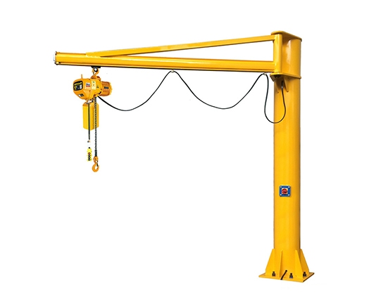
Light structure, beautiful shape.
Good technology, long life.
Flexible and smooth operation, safe and reliable.
Widely application, low cost performance.
Load capacity up to 10 tons
Span up to 20m
Long-travel speed up to 30m/min
Cross-travel speed up to 20m/min
Lifting speed up to 8m/min
Non-standard specifications on request
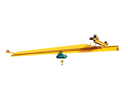
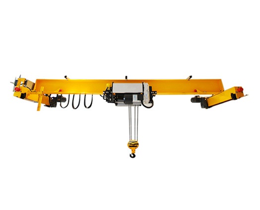
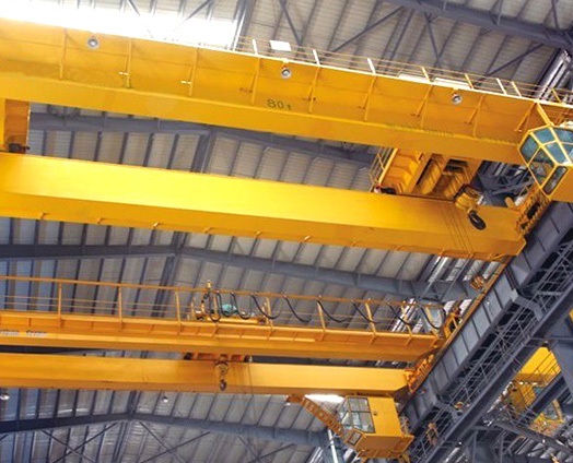
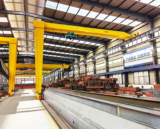
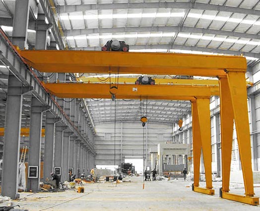
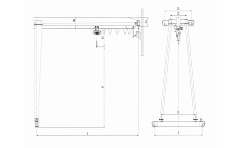
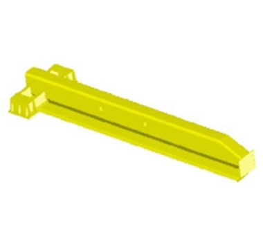 | Bridge 1. Main girder is the major bearing carrier of hoist style crane and also the runway of the electric hoist. 2. Welded by U-steel and I-beam which made of pressed steel. 3. Steel material is Q235B or Q345B (similar to foreign Fe37 or Fe52). 4. Bridge camber (F) is (1/1000~1.4/1000) S. Max. camber is located in the middle of span within S/10. 5. Electric hoist trolley travels on the flange of the I beam. When the hoist located in the middle of main girder, the full load natural frequency should no less than 2Hz. 6.The crane bumpers are installed on the both ends of the main girder to ensure the safety of trolley travelling. |
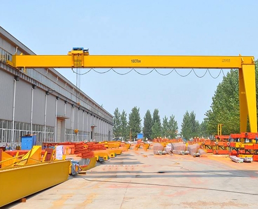
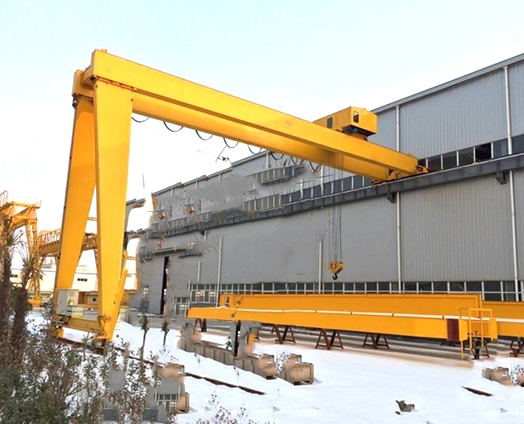
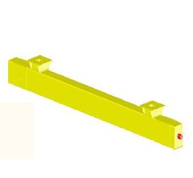
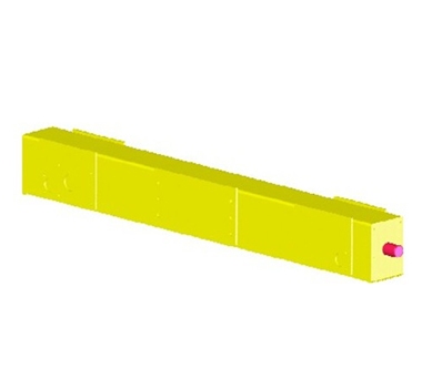 | Upper beam, bottom beam 11.Upper and bottom beams are the main basic support of the main girder and loading and also is the link between main girder and travelling mechanism. It is one of the principal bearing carrier of crane's metal structure. 2.Box structure is mainly welded by steel plate with the character of light, rigid, nice and good welding technology. 3.Bumpers are installed on the bottom of beam. 4.Upper beam locate above the upper rail and the bottom beam under the bottom rail. 5.Generally, the bottom beam is longer than upper beam and the length depends on the length and angle of landing leg. |
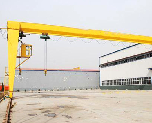
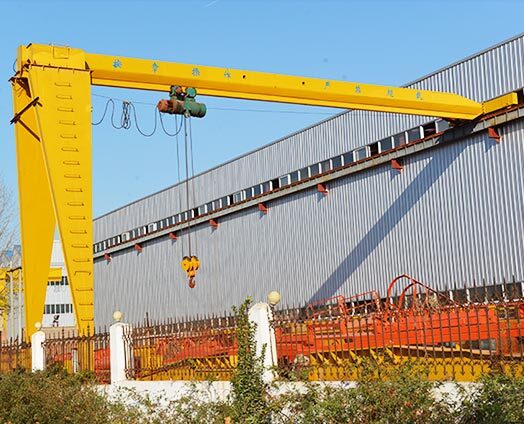
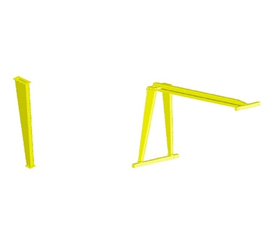 | Landing Leg 1.Consists of top flange, bottom flange and box structural support beams welded by steel plate. 2.The landing leg become conversion section structure which is big end up at the result of big top flange and small bottom flange. This structure can bear the loading of vertical and horizontal direction effectively. 3.Main girder and upper end beam are connected with bolt to modify the flange hanging connect structure. Simple structure, easy installation and convenient to transport and storage. 4.Main girder and the two legs which symmetrically arranged on the two sides of it are connected with bolts to fasten the two flanges. And the space between two legs become wide below narrow with a certain angle to shape kind of "A" structure, thus improve the stability. 5.The landing leg and bottom beam are connected with bolt. |
 | Ladder Landing Welded by angle steel, flat steel, round steel, etc. Connected with bolts and the angle steel that welded on the landing leg to avoid on-site welding. Easy assembly. |
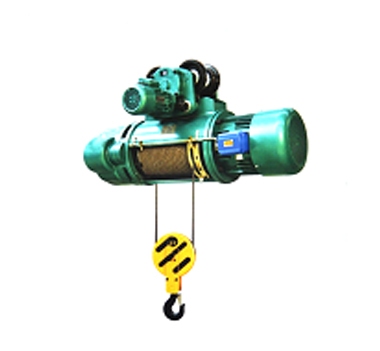 | Other parts 1.Lifting Mechanism - CD or MD wire rope hoist Crane Traveling Mechanism Drive separately, composed of traveling motor, traveling reducer, wheel group, etc. |
|
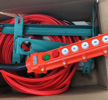
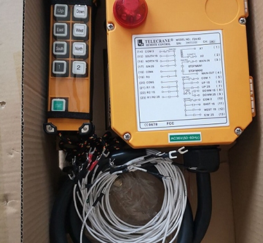
Pendant control
Remote control
Cabin control | Operation 1.Ground control and cabin control 2.The cabin has open style, close style,can fixed on left or right 3.The open direction include end open,side open or top open 4.The cabin includes special small room for single-girder and capsule cabin 5.Ground control has handle and remote control, do not need to set up special driver 6.Users can choose as you need |
Overall Organization Drawing
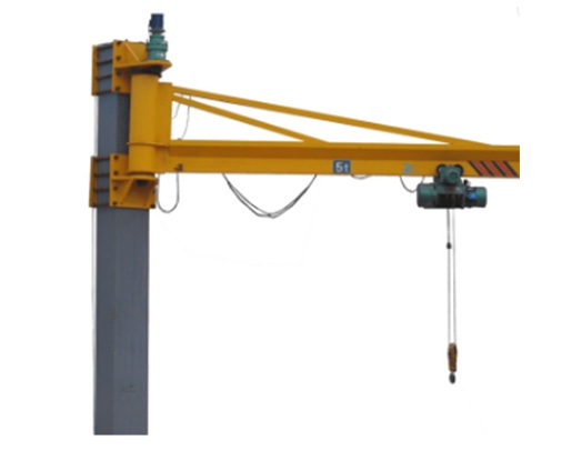
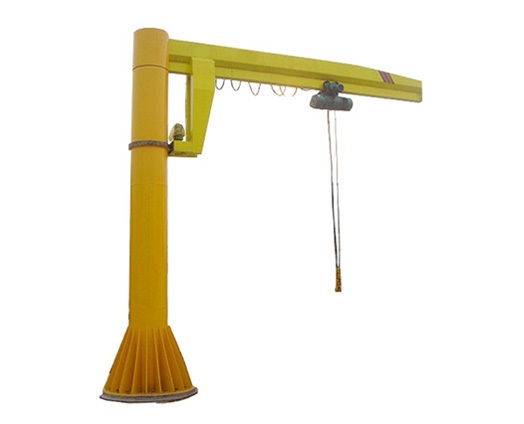
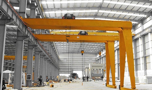
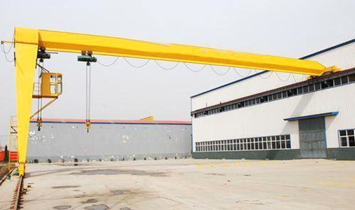
Application examples
Please Feel free to give your inquiry in the form below.we will reply you in 24 hours.