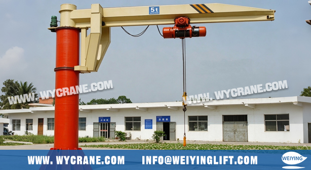
Choosing the right
type of
jib crane is only half the job. The other half — the one that determines whether the crane actually works on your floor — is
sizing: calculating the five numbers that define the machine before you order it.
-
Rated capacity — how much it can lift, at your actual radius
-
Reach (working radius) — how far the hook must travel from the column
-
Hook coverage area — the real usable zone, not the theoretical circle
-
Column position — where the support must stand (and what it loads)
-
Clearances — the vertical and swing space the crane needs to live
If you’ve already decided a jib crane is the right solution for your workstation, this guide walks through the calculation logic, step by step, with formulas and a complete worked example at the end.
Every calculation here is based on the most conservative working condition: the heaviest workpiece, at the farthest pickup point.
Step 1 — Calculate the Required Rated Capacity
The headline capacity on a jib crane brochure is almost never the number you size against. Start with the design load:
Design load = heaviest workpiece + lifting device (fixture, clamp, spreader) × service factor
Practical rules:
-
Add the weight of the lifting device itself — a vacuum lifter or mold clamp can easily add 100–200 kg.
-
Apply a service factor of 1.2–1.25 to cover dynamic effects: hoist starting shock, load swings, and slight overloads from scale uncertainty.
-
Confirm with the manufacturer whether the hoist’s self-weight is included in their capacity definition — practice varies.
Quick example: 800 kg workpiece + 120 kg clamp = 920 kg design load. × 1.2 service factor = 1.10 t required at the actual working radius.
One more check for high-cycle duty: the crane’s duty class (FEM / ISO rating) determines whether it can live near its rated capacity all day. If you lift close to the limit every cycle, size up a capacity step — the price difference is small compared to premature brake and rope wear.
Step 2 — Determine the Working Radius (Reach)
This is where most sizing errors begin. Two definitions must be nailed down:
-
Arm length is measured from the column centerline — not from the column face. A 5 m arm on a 400 mm column reaches about 4.8 m from the column surface; if you measured from the face, you’ve just lost 200 mm of real reach.
-
Working radius = the farthest horizontal point the hook must reach, which is not always the workpiece center. With offset lifting devices, the hook position differs from the load’s center of gravity.
Method: draw a top-view layout of the workstation and mark three points:
-
Load pickup point (pallet, bin, conveyor)
-
Work point (machine table center, assembly position)
-
Set-down point (finished parts container)
Then:
Required arm length = distance from planned column centerline to the farthest of the three points + 300–500 mm margin
The margin matters. A hook operating at the absolute tip of the arm leaves zero tolerance for layout changes and forces the operator to run the trolley against the end stop every cycle — accelerating wear on the trolley bumpers and rope guide.
Step 3 — Read the Load-at-Radius Curve Correctly
A jib arm is a cantilever beam: bending moment = load × radius. Therefore allowable capacity decreases as the hook moves outward. This is the single most misunderstood point in jib crane sizing.
The core verification is:
Required capacity @ radius R ≥ design load — checked against the manufacturer’s load-radius table, not the nameplate.
Example, continued from Steps 1–2: you need 1.10 t at 4.5 m. A “2 t × 5 m” crane sounds adequate — and it is, at 4.5 m, where the table allows 1.6 t. But at the full 5 m arm tip, the same crane may allow only 1.2 t. Two consequences:
Always request the manufacturer’s load-radius chart for the exact configuration, not just the catalog cover value. And record which radius each lift actually requires: “radius ≤ 4.5 m” should be written into your lifting plan for the workstation.
Step 4 — Map the Hook Coverage Area
The coverage of a floor-mounted jib is a ring, not a circle — and the hole in the middle matters.
The blind zone: the hook cannot reach the arm root area, because the column occupies space and the trolley has a minimum outreach from the column face. The inner unusable radius r is typically 0.5–1.0 m depending on structure size.
Effective coverage area A = (θ / 360) × π × (R² − r²)
where θ is the rotation angle (360° for floor-mounted, typically 180–200° for wall-mounted) and R is the working radius.
Verification: all three working points (pickup, work, set-down) must fall inside the effective ring band, not merely inside the theoretical circle. Also check that the blind zone doesn’t collide with a pallet lane or pedestrian route you’d assumed was covered.
Articulating jibs are different: their coverage is a joint envelope, not a standard annulus. Ask the manufacturer for a rotation envelope drawing and overlay it directly onto your layout plan — this is the only reliable way to verify an articulating arm.
For installations with multiple jib cranes, draw the full swing circle of each unit and check for overlap conflicts between adjacent arms.
Step 5 — Position the Column and Check Installation
Column location has the highest lock-in cost of any decision in this guide: arm length can be increased later; a poured foundation cannot be moved.
Positioning principles:
-
Cover all three working points with margin (Steps 2 and 4).
-
Keep the column out of equipment zones, forklift lanes, and escape routes.
-
Confirm the foundation can actually be built there — underground services and thin slabs are common killers.
Foundation checks (floor-mounted):
-
Bearing capacity of the soil or slab beneath the base plate.
-
Overturning moment: M = rated load × working radius. In our example: 1.1 t × 4.5 m ≈ 49.5 kN·m. Manufacturers supply a foundation load table (vertical force, overturning moment, horizontal shear) — hand this directly to your structural engineer.
-
Anchor bolt specification and embedment depth per the manufacturer’s foundation drawing.
Wall-mounted units: only structural columns are acceptable supports — never infill or cladding walls. The wall bracket transfers an overturning moment into the building frame; confirm the column can accept the moment values from the manufacturer’s table.
Step 6 — Verify Clearances (Overhead, Swing, and Approach)
Vertical stack — the headroom equation:
Required building height ≥ arm underside clearance + hoist body height + rigging height + workpiece height + safety margin (min. 300 mm)
Work through the stack with real catalog dimensions, and check both extremes: the highest point of the lifted load path against roof trusses, lights, sprinklers, and any overhead crane runway — and the arm’s upper surface against the same obstacles in every rotation position.
Swing envelope: the arm sweeps a vertical cylinder. No fixed obstructions — cable trays, ductwork, diagonal bracing, light fittings — may intrude into that cylinder at any height the arm occupies.
Equipment interference: check machine tool enclosures in their fully open position, tool changer rotation, and transfer table travel. A loading operation that works with the guard closed may collide with it open.
Articulating arms: verify two envelopes — fully folded for stowage and fully extended for work.
Worked Example: Sizing a Jib Crane for a CNC Cell
Scenario: machine loading cell; workpiece 800 kg + clamp 120 kg; pickup point 2.8 m from column centerline; machine table center 4.2 m; parts bin 4.6 m; building clear height 6 m.
| Step |
Calculation |
Result |
| 1. Design load |
920 kg × 1.2 |
1.10 t required |
| 2. Arm length |
4.6 m + 0.4 m margin |
≥ 5.0 m |
| 3. Capacity @ radius |
2t × 5m chart: 1.6 t @ 4.5 m ✓ / 1.2 t @ 5.0 m (tip) |
OK below 4.5 m; tip restricted or upsize |
| 4. Coverage |
θ=360°, R=5.0 m, r=0.8 m → all points inside ring |
✓ |
| 5. Foundation |
M = 1.1 t × 4.5 m ≈ 49.5 kN·m |
Match to mfr. foundation table |
| 6. Headroom |
6 m − arm − hoist − clamp − workpiece ≥ 300 mm margin |
✓ (verify with catalog dims) |
5 Common Sizing Mistakes
-
Using nameplate capacity instead of capacity at radius — the #1 cause of undersized jib cranes.
-
Measuring arm length from the column face — losing 200–400 mm of real reach.
-
Forgetting the lifting device’s weight and load eccentricity.
-
Planning coverage as a full circle without subtracting the blind zone.
-
Checking headroom for the hoist only — omitting rigging and workpiece height.
Data Checklist to Send Your Supplier
-
Maximum and routine workpiece weights
-
Lifting device weight and hook eccentricity
-
Coordinates of pickup / work / set-down points and farthest radius
-
Building clear height and obstacle list (trusses, lights, ductwork, overhead crane)
-
Floor type and permitted excavation depth / available structural columns
-
Shift cycle rate (for duty class), plus any explosion-proof or outdoor requirements
Provide these six items and a manufacturer can return the complete sizing package in one pass: load-radius chart, foundation loads, and rotation envelope drawing.
Conclusion
Sizing a jib crane is not one decision — it’s a chain of five calculations, and the chain is only as strong as its weakest link. An correctly rated capacity fails if the arm is measured from the wrong reference point. A perfectly sized arm fails if the blind zone swallows your set-down pallet. A flawless crane on paper fails if a roof truss sits inside its swing envelope.
Work the sequence in order and never skip ahead: design load → working radius → capacity at that radius → effective coverage ring → column position and foundation loads → clearance stack. Write every number down on a single sizing sheet, attach it to the purchase specification, and hand the foundation loads to your structural engineer before any concrete is poured.
Get these five numbers right, and the jib crane disappears into your workflow — silent, instant, and reliable for decades. Get one of them wrong, and every shift will remind you. An hour of calculation is the cheapest insurance your workstation will ever get.
FAQ
How far can a jib crane reach?
Standard floor-mounted jib arms run up to about 7–8 m; beyond that, capacity at the tip drops steeply and other solutions usually win. The practical reach for a given capacity is defined by the load-radius chart, not by the arm length alone.
How do I calculate jib crane capacity?
Calculate the design load (workpiece + lifting device), multiply by a 1.2–1.25 service factor, then verify that the manufacturer allows that load at your required working radius on the load-radius chart.
How much clearance does a jib crane need above the load?
Stack arm underside + hoist body + rigging + load height, and keep at least a 300 mm safety margin to the nearest overhead obstruction. Verify in both the raised and travel positions, through the full rotation.
About us

With 34 years of manufacturing experience and 12 years of export expertise, we have built a dual advantage of professional qualifications and a global presence. Our business covers more than 100 countries and regions across Asia, Europe, the Americas, Africa, and Oceania. We are certified under the ISO management system and hold CE product certifications. Our main product lines include six major series—electric hoists, electric winches, gantry cranes, bridge cranes, marine cranes, and portal cranes—comprising nearly 100 different models.
If you want to learn more, please contact us.
E-mail address: info@weiyinglift.com
Website:www.wycrane.com